[repost] Exception and Interrupt handling in the MIPS architecture

Introduction

In this unit, you will learn how to add interrupt and exception support to your multicycle CPU design. For additional information, please refer section 5.6 and appendix A in the Hennessy and Patterson textbook. Note: you will only be implementing a subset of the exception and interrupt functionality of the MIPS architecture. Therefore, use this page as your definitive source of information regarding this unit.

Exceptions and Interrupts defined

Exceptions and interrupts are unexpected events that disrupt the normal flow of instruction execution. An exception is an unexpected event from within the processor. An interrupt is an unexpected event from outside the processor. You are to implement exception and interrupt handling in your multicycle CPU design.

When an exception or interrupt occurs, the hardware begins executing code that performs an action in response to the exception. This action may involve killing a process, outputting a error message, communicating with an external device, or horribly crashing the entire computer system by initiating a “Blue Screen of Death” and halting the CPU. The instructions responsible for this action reside in the operating system kernel, and the code that performs this action is called the interrupt handler code. You can think of handler code as an operating system subroutine. After the handler code is executed, it may be possible to continue execution after the instruction where the execution or interrupt occurred.

Exceptions: Types

For your project, there are three events that will trigger an exception: arithmetic overflow, undefined instruction, and system call.

Arithmetic overflow occurs during the execution of an add, addi, or sub instruction. If the result of the computation is too large or too small to hold in the result register, the Overflow output of the ALU will become high during the execute state. This event triggers an exception.

Undefined instruction occurs when an unknown instruction is fetched. This exception is caused by an instruction in the IR that has an unknown opcode or an R-type instruction that has an unknown function code.

System call occurs when the processor executes a syscall instruction. Syscall instructions are used to implement operating system services (functions).

Interrupts

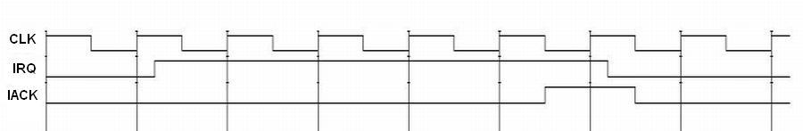
We also want to have to ability to service external interrupts. This is useful if a device external to the processor
needs attention. To do this, we’ll add 2 pins to the processor. The first pin, called IRQ (interrupt request), will be
an input that will allow an external device to interrupt the processor. Since we don’t want the processor to service any
external interrupts before it is finished executing the current instruction, we may have to make the external device
wait for several clock cycles. Because of this, we need a way to tell the external device that we’ve serviced its
interrupt. We’ll solve this problem by adding the second pin, called IACK (interrupt acknowledge), that will be an
output. The following waveform defines the timing for external interrupt requests.

Fig1

What to do when an exception or interrupt occurs

When an exception or interrupt occurs, your processor may perform the following actions:

  • move the current PC into another register, call the EPC
  • record the reason for the exception in the Cause register
  • automatically disable further interrupts or execptions from occuring, by left-shifting the Status register
  • change control (jump) to a hardwired exception handler address

To return from a handler, your processor may perform the following actions:

  • move the contents of the EPC register to the PC.
  • re-enable interrupts and exceptions, by right-shifting the Status register

Dealing with multiple types of exceptions and interrupts

In a situation where multiple types of exceptions and interrupts can occur, there must be a mechanism in place where different handler code can be executed for different types of events. In general, there are two methods for handling this problem: polled interrupts and vectored interrupts.

  1. The processor can branch to a certain address that begins a sequence of instructions that check the cause of the exception and branch to handler code for the type of exception encountered. This is called polled exception handling.
  2. The processor can branch to a different address for each type of exception. Each exception address is separated by only one word. A jump instruction is placed at each of these addresses that forces the processor to jump to the handler code for each type of exception. This method is called vectored exception handling.

MIPS uses the first method (polled interrupts), so we’ll implement exception handling that way. So, in our case, all exceptions will cause the processor to jump to a “hardwired” instruction address. A sequence of instructions starting at this address will check the cause of the exception and act accordingly. We will set this address to 00000004 (in hex). Also, we’ll need to use the Cause register to record the cause of the exception or interrupt before jumping to the handler code.

Cause register

The Cause register is a 32-bit register, but only certain fields on that register will be used. Bits 1 down to 0 will be set to describe the cause of the last interrupt/exception. The following table codes the interrupt/exception causes:

Number Name Description
00 INT External Interrupt
01 IBUS Instruction bus error (invalid instruction)
10 OVF Arithmetic overflow
11 SYSCALL System call

Disabling interrupts and exceptions

We require a way to disable interrupts and exceptions. This is necessary to prevent exceptions and interrupts from
occuring during handler execution. In order to be able to do this, we need an additional register that can be used to
mask exception and interrupt types. This is called the Status register.

Status register

The status register is also a 32-bit register. It too, only has certain fields that are used by the processor. Bits 3 down to 0 will define masks for the three types of interrupts/exceptions. If an interrupt/exception occurs when its mask bit is current set to 0, then the interrupt/exception will be ignored. The mask bits are used according to the following table:

Bit Interrupt/exception
3 INT
2 IBUS
1 OVF
0 SYSCALL

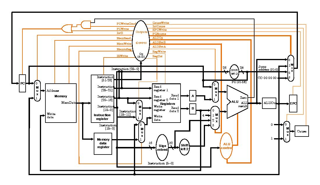
Control for exceptions

You will need to add control and datapaths to support exceptions and interrupts. When an exception or interrupt occurs, the following must be done:

EPC <= PC
Cause <= (cause code for event)
Status <= Status << 4
PC <= (handler address)

To return from an exception or datapath, the following must be done:

PC <= EPC
Status <= Status >> 4

You will also have to add control to support four additional instructions, mfc0, mtc0, syscall, and rte.

Fig2

Additional instructions needed

Several instructions must be added to your instruction set in order to use the interrupt/exception functionality of your processor. These instructions are mfc0 rt,rd and mtc0 rd,rt, which stand for “move from coprocessor 0” and “move from coprocessor 0”. The new registers that facilite interrupt and exception handling, Status, Cause, and EPC, can be accessed via these instructions. These new instructions transfer data between the exception registers and the general-purpose registers. Also, you will need the syscall instruction. These instructions are encoded in the following way:

syscall

Executes a system call. The system call number should be set in register $v0 prior to executing the system call.

31-26 25-6 5-0
000000 00000000000000000000 001100

rfe

Return from exception.

31-26 25 24-6 5-0
010000 1 0000000000000000000 010000

mfc0 rd, rt

Moves data from coprocessor 0 register rt to general purpose register rd.

31-26 25-21 20-16 15-11 10-0
010000 00000 rt rd 00000000000

mtc0 rd, rt

Moves data from general purpose register rt to coprocessor 0 register rd.

31-26 25-21 20-16 15-11 10-0
010000 00100 rt rd 00000000000

The following table defines coprocessor 0’s register set:

Register name Register number Usage
Status 12 Interrupt mask and enable bits
Cause 13 Exception type
EPC 14 Register containing the following address of the instruction where the exception occurred

转-FPGA复位电路的实现及其时序分析

Note:原文地址http://blog.chinaaet.com/coyoo/p/34513#

概述

大部分的FPGA和ASIC设计都是基于大量flip-flop或者寄存器的同步系统设计,所以所有这些同步单元的起始状态或者将要返回的状态是一个已知状态(罗辑‘1’或者‘0’)就显得非常重要。这一个功能通常都是由一个“reset”电路来完成。一个设计或者一个FPGA器件通常都使用或输入有一个或者多个复位信号,同时伴随一些其它控制逻辑电路来共同完成此“复位”功能。本文探讨各种复位电路,同步的、异步的以及同步化的异步复位,分析这些不同复位电路的优缺点。展现实现这些不同复位电路的技巧,并使用Altera的TimeQuest时序分析器来对它们进行正确的时序分析。

我们通常意义上的同步电路通常是由两种复位方式来进行电路的复位,即同步复位和异步复位。同步复位的复位频率同步与寄存器的时钟域,而异步复位按性质,其影响寄存器和寄存器的时钟之间没有确定的时序关系。正因为如此,获取异步复位信号的时序关系是非常困难的。如前所述,这里即将讨论的第三种复位,无法更好的为其命名,大家更多的时候叫其同步化的异步复位,就是一个异步复位被同步到系统时钟域,有时候大家也称这种过程为异步复位同步释放。这种同步化的异步复位,具有同步复位的好处,却没有同步复位的缺点;同时他们还避免了纯粹异步复位的缺陷。后面论述中我们将看到,这种同步化的异步复位应该是FPGA电路设计时复位电路的首选。

同步复位

所谓同步复位是基于这样的一个前提,即服务信号只是在寄存器时钟的有效沿时影响该寄存器的状态。同步的典型优点是它们能确保电路为百分百的同步电路。同步复位的另一个优点是它们的时序可以很容易被静态时序分析器比如Altera的TimeQuest分析器分析。由于同步复位信号是被时钟启动(Launch)和锁存(Latch),而启动和锁存的时钟彼此同步,所以复位信号的到达时间(Arrival time)和所需时间(Required time)就能很轻易的确定并进行正确的slack分析。同步复位还有一个优点是它们更易于仿真当它们作用于一些基于周期机制的功能模块时。

同步复位也有自己的缺点。例如,它们可能要求脉冲宽度满足一定要求,以保证在需要复位的时钟沿复位信号是有效的,所以这时候电路中也许需要脉冲延伸器或者说脉冲扩展器。也许更重要的是,同步复位总是需要一个时钟来完成对电路的复位。如果因为某些因素导致复位信号的启动时钟沿错误,那么就会导致整个电路复位功能的失败。

在Altera
FPGA中,有两种方法可以将复位信号送达寄存器。一种是随数据门控输入,如图1所示,另一种是使用LAB宽控制信号,如synclr,如图2所示。

FPGA principle

  1. 时序电路建模时,用非阻塞赋值
  2. 锁存器电路建模时,用非阻塞赋值
  3. 用always块写组合逻辑时,采用阻塞式赋值
  4. 在同一个always块中,同时建立时序和组合逻辑电路时,用非阻塞赋值
  5. 在同一个always块中,不要同时使用阻塞赋值和非阻塞赋值
  6. 不要在多个always块中为同一个变量赋值
  7. 在赋值时,不要使用#0延迟

[转载]嗯,让我们彻底搞懂C/C++函数指针吧(三)

原创作品,允许转载,转载时请务必以超链接形式标明文章 原始出处 、作者信息和本声明。否则将追究法律责任。http://hipercomer.blog.51cto.com/4415661/792302

3.6 使用函数指针数组

函数指针有意思的地方在于,它使用从0到n-1这个n个连续的整数下标直接映射到函数上。
和前面一样,我们也是类比着定义普通指针数组来定义函数指针数组。首先,考虑一个浮点数指针数组,数组的长度为10.我们都知道用下面的形式来定义:

float * pFloatArray[10];

从形式上分析,用中括号明确了是定义指针变量还是定义指针数组这个语义。用数字10明确了这个数组能容纳多少个函数指针这个语义。形式上看,中括号是紧接在指针名称的后面再中括号里面是一个需要在编译时期间就能够确定的常数。
现在我们来类比函数指针数组的定义,定义一个指向函数指针类型为:float (*)(float,float)的函数指针数组,数组长度为10.正确的形式为:

float(* pFunctionArray[10])(float,float)

[转载]嗯,让我们彻底搞懂C/C++函数指针吧(二)

原创作品,允许转载,转载时请务必以超链接形式标明文章 原始出处 、作者信息和本声明。否则将追究法律责任。http://hipercomer.blog.51cto.com/4415661/792301

3.4 函数指针作为参数

如果你已经明白了函数的参数机制,而且完全理解并实践了3.3节的内容,这一节其实是很简单的。只需要在函数的参数列表中,声明一个函数指针类型的参数即可,然后再调用的时候传给它一个实参就可以了。你可以这么想象,就是把函数指针的赋值语句的等号换成了形参和实参结合的模式就行。
下面给一个简单的例子:

1
2
3
4
5
6
7
8
9
10
11
12
13
14
15
16
17
18
19
20
21
22
23
24
25
26
27
28
29
30
31
32
33

/*
* Author :Choas Lee
* Date :2012-02-28
*/

#include<stdio.h>

float add(float a,float b){return a+b;}

float minus(float a,float b){return a-b;}

float multiply(float a,float b){return a*b;}

float divide(float a,float b){return a/b;}

int pass_func_pointer(float (*pFunction)(float a,float b))

{
float result=pFunction(10.0,12.0);
printf("result=%f\n",result);

}

int main()
{
pass_func_pointer(add);
pass_func_pointer(minus);
pass_func_pointer(multiply);
pass_func_pointer(divide);

return 0;
}

输出结果为:

[转载]嗯,让我们彻底搞懂C/C++函数指针吧(一)

原创作品,允许转载,转载时请务必以超链接形式标明文章 原始出处 、作者信息和本声明。否则将追究法律责任。http://hipercomer.blog.51cto.com/4415661/792300

摘要:这篇文章详细介绍C/C++的函数指针,请先看以下几个主题:使用函数指针定义新的类型、使用函数指针作为参数、使用函数指针作为返回值、使用函数指针作为回调函数、使用函数指针数组,使用类的静态函数成员的函数指针、使用类的普通函数成员的指针、定义函数指针数组类型、使用函数指针实现后绑定以及在结构体中定义函数指针。如果您对以上这几个主题都很了解,那么恭喜您,这篇文章不适合您啦~。在一些开源软件中,如Boost, Qt, lam-mpi中我们经常看到函数指针,本文目的是彻底搞定函数指针的语法和语义,至于怎样将函数指针应用到系统架构中不在此文的讨论范围中。各位看官,有砖拍砖啊~

1. 无处不见的函数指针

使用函数指针可以设计出更优雅的程序,比如设计一个集群的通信框架的底层通信系统:首先将要每个消息的对应处理函数的指针保存映射表中(使用STL的map,键是消息的标志,值是对应的函数指针),然后启动一个线程在结点上的某个端口侦听,收到消息后,根据消息的编号,从映射表中找到对应的函数入口,将消息体数据作为参数传给相应的函数。我曾看过lam-mpi在启动集群中每个结点的进程时的实现,该模块的最上层就是一个结构体,这个结构体中仅是由函数指针构成,每个函数指针都指向一个子模块,这样做的好处就是在运行时期间可以自由的切换子模块。比如某个子模块不适合某个体系结构,只需要改动函数指针,指向另外一个模块就可。
在平时的程序设计中,经常遇到函数指针。如EnumWindows这个函数的参数,C语言库函数qsort的参数,定义新的线程时,这些地方函数指针都是作为回调函数来应用的。
还有就是unix的库函数signal(sys/signal.h)(这个函数我们将多次用到)的声明形式为:

void (*signal)(int signo,void (*func)(int)))(int);

C/C++ 函数指针

需要明确几点:

  1. C/C++函数指针都需要原型
  2. C++对象中,对于静态/非静态函数,只有一份

函数指针原型

  1. C

    1
    返回类型 (*函数指针名称)(参数类型,参数类型,参数类型,…)
  2. C++

    1
    返回类型 (类名称::*函数成员名称)(参数类型,参数类型,参数类型,….)

示例

  1. C

    1
    2
    3
    4
    5
    6
    7
    8
    9
    10
    11
    void FunApp(void)
    {

    // Do something
    }


    typedef void (*pFun_t)(void);

    pFun_t pFun = FunApp;

    pFun();
  2. C++

    1
    2
    3
    4
    5
    6
    7
    8
    9
    10
    11
    12
    13
    14
    15
    16
    17
    18
    // class
    class MyClass
    {
    public:
    MyClass();
    ~MyClass();

    void printname(void);
    };

    typedef void (MyClass::*pFun_t)(void);

    MyClass mClass;

    pFun_t pFun = &MyClass::printname;

    // Call Function
    mClass.*pFun();

Qt Visual Studio Add-in Frequently Asked Questions

ref: http://doc.qt.io/vs-addin/vs-addin-faq.html

Why is code completion not working?

1 You’re implementing a slot…

Visual Studio can only provide code completion as long as it understands the code. Unfortunately, it does not know how to handle the Qt keyword slots in the header file. This means that the respective function body is foreign to the code model and no code completion will be provided. You can workaround the problem be placing a ‘;’ after the colon of the slots keyword in the class declaration.

Note: Remember to remove the ‘;’ when exporting the project as the code might not compile with older Unix compilers.

1
2
3
4
5
6
7
8
9

class MyClass {
Q_OBJECT

public slots:;
void doSomething();

...
};

2 You are referencing objects from a .ui file

The Visual Studio code model parser only parses C++ sources, meaning that widgets or objects defined in .ui files will not be accessible. To workaround the problem, the Qt Visual Studio Add-in automatically generates C++ code from the .ui file by saving the file and running uic on it. This step is done everytime the project is built. If the code completion does not work, try to rebuild the project. It is possible that you have to wait some time, before code completion fully works after updating an .ui file. For more information, you can refer to the Modifying Project Properties section.

3 It still does not work

You should refresh the code model, Intellisense. This is done by opening the solution explorer, invoking the context menu of the project and activating the item Update Intellisense.

公司类别

1 公司类别

  1. 有限责任公司及其分支机构登记
  2. 股份合作公司及其分支机构登记
  3. 股份有限公司及其分支机构登记
  4. 外商投资企业及其分支机构登记
  5. 外国(地区)企业常驻代表机构登记
  6. 外国(地区)企业从事生产经营活动登记
  7. 外商投资合伙企业及其分支机构登记
  8. 个人独资企业及其分支机构登记
  9. 合伙企业及其分支机构登记
  10. 个体工商户登记
  11. 非公司企业法人及其分支机构登记
  12. 企业集团登记

2 适合创业公司的类别

  1. 有限责任公司及其分支机构登记
  2. 个人独资企业及其分支机构登记
  3. 合伙企业及其分支机构登记
  4. 个体工商户登记

3 详细信息如下

1. 有限责任公司及其分支机构登记

条  件
1.    股东符合法定人数
2.    股东出资达到法定资本最低限额
3.    股东共同制定公司章程
4.    有公司名称,建立符合有限公司要求的组织机构
5.    有公司住所

申请材料
1.    拟任法定代表人签署的《企业设立登记(一照一码)申请书》(原件1份);
2.    经办人身份证明(复印件1份,验原件);
3.    全体股东(发起人)签署的章程(原件1份);
4.    股东(发起人)的主体资格证明(复印件1份,自然人身份证明验原件,单位资格证明加盖公章,注明“与原件一致”。股东为深圳市商事主体的可以免提交主体资格证明);
5.    法定代表人、执行董事/董事长、董事、监事、经理的任职文件(原件1份)及其身份证明(复印件1份)(法定代表人身份证明验原件;执行董事/董事长、董事、监事、经理身份证明的复印件上需注明“与原件一致”并由法定代表人签字);
6.    法律、行政法规和国务院决定规定设立公司必须报经批准的,提交有关的批准文件或者许可证书(复印件1份,核对原件)(注:可由我局通过监察局共享系统查验相关信息的,可无需提交;否则需提交纸质文件);
7.    一人(自然人)独资有限公司应提交一人有限公司承诺书。

2. 个人独资企业及其分支机构登记

条  件
1.    投资人为一个自然人;
2.    有合法的企业名称;
3.    有投资人申报的出资;
4.    有符合规定的生产经营场所和必要的生产经营条件;
5.    有必要的从业人员。

申请材料
1.    投资人签字的《企业设立登记四证申请书》(原件1份);
2.    经办人身份证明(复印件1份,验原件);
3.    投资人身份证明(复印件1份,验原件);
4.    法律、行政法规或者国务院规定设立企业须经批准的,还应当提交有关批准文件(原件1份)(注:可由我局通过监察局共享系统查验相关信息的,可无需提交;否则需提交纸质文件)。

3. 合伙企业及其分支机构登记

条  件
1.    有二个以上合伙人。合伙人为自然人的,应当具有完全民事行为能力;
1.    有书面合伙协议;
1.    有各合伙人认缴或实际缴付的出资;
1.    有合伙企业的名称;
1.    有经营场所和从事合伙经营的必要条件。

申请材料
1.    全体合伙人签署的《企业设立登记(一照一码)申请书》(原件1份);
2.    经办人身份证明(复印件1份,验原件);
3.    全体合伙人的主体资格证明(复印件1份,自然人身份证明验原件,单位资格证明加盖公章,注明“与原件一致”;合伙人为深圳市商事主体的可以免提交主体资格证明);
全体合伙人签署的合伙协议书(原件1份);
4.    如合伙企业协议委托一个或数个合伙人执行合伙事务的,提交全体合伙人签署的执行合伙事务的合伙人的委托书(原件1份);
5.    执行事务合伙人是法人或其他组织的,还应当提交其委派代表的委托书(原件1份)和委派代表的身份证明(复印件1份,自然人身份证明验原件,单位资格证明加盖公章,注明“与原件一致”;合伙人为深圳市商事主体的可以免提交主体资格证明);
6.    全体合伙人对各合伙人认缴或实缴出资的确认书。合伙人以实物、知识产权、土地使用权或者其他财产权利出资,经合体合伙人协商作价的,提交全体合伙人签署的协商作价确认书(原件1份);经全体合伙人委托法定的评估机构作价的,提交法定评估机构出具的评估作价证明(原件1份)(注:可由我局通过监察局共享系统查验相关信息的,可无需提交;否则需提交纸质文件);
7.    法律、行政法规规定设立特殊的普通合伙企业,需要提交合伙人的职业资格证明的,应提交相应证明(注:可由我局通过监察局共享系统查验相关信息的,可无需提交;否则需提交纸质文件)。

4. 个体工商户登记

条  件
1.    有经营能力的公民、从事工商经营的;
2.    经营范围不属于法律、行政法规禁止进入的行业。

申请材料
1.    经营者签署的《个体工商户设立登记(一照一码)申请书》(原件1份);
2.    经办人身份证明(复印件1份,验原件);
3.    经营者的身份证明(复印件1份,验原件)【身份证、护照、通行证、军官证、退休证及其他能证明合法身份的证件;
香港居民提交永久性居民身份证、特区护照复印件(任选其一);澳门居民提交永久性居民身份证、特区护照复印件(任选其一);
台湾居民提交台湾居民身份证、台湾居民来往大陆通行证或旅行证复印件(任选其一)】(注:只有港澳永久居民才能办理港澳个体户)。

更多资料,访问前海网站

USB IN事务的注意事项

因为USB属于主机控制总线,所以Device端要发送数据时,只能被动的等待轮询

所以,对于USB IN事务的首次触发,需要特殊对待

常用的方法有

  1. 先设置有效长度为0,然后使能IN端点
    这样,HOST就可以直接发送IN事务,获取0字节长度,然后触发Device的IN中断;
    Device在触发IN中断后,就可以发送有效数据了
  2. 先设置IN断电为STALL状态,HOST要读取数据时,只有先发送一个OUT事务,通知Device把数据准备好,然后HOST再次去请求IN事务

高速USB的不二选择,NXP LPC Xpresso4337 Development Board 体验

0 序

最近在做高速USB(480Mbps)项目,用STM32需要外接一个PHY,比如USB3300芯片,额外增加了硬件成本,于是找了一下自带高速USB PHY的芯片,别说,还真有!而且性能非常劲爆

NXP LPC4300系列芯片

芯片主要的特性:

  1. 204MHz M0/M4双核芯片
  2. 1M Flash
  3. 2个CAN接口
  4. 2个高速USB2.0接口,自带PHY
  5. 自定义IO接口,速度高达100MHz
  6. 自带LCD控制器,支持1024 H x 768 V

额外的特性,请访问LPC43xx主页
反正NXP LPC系列MCU各种牛X,秒杀STM32F4系列,,,

1 LPC Xpresso4337 开发板

LPC针对4300系列,提供2款评估板

STM32 F410RB Nucleo

STM32F410RB Nucleo测评

1 综述

最近拿到一块STM32F410的Nucleo板子,给大家介绍一下ST新出的F410系列

ST32F410

2 STM32F410芯片

F410是ST新推出的一款M4内核MCU,主频100MHz,主打低功耗,动态功耗竟然达到了89uA/MHz,Stop模式待机电流6uA。堪称里程碑!

什么概念呢?
在保持同等运算性能的情况下,功耗是F405的1/10,直逼L4系列,要知道L4是ST的低功耗,高性能产品线代表作品

F410的出现给大家多了一个M4选择:功能强劲,价格足够低,低功耗能力非常突出

我的新产品,准备用这颗F410来做

2. 1 主打特性
  1. Dynamic Efficiency Line with BAM (Batch Acquisition Mode)
    Core: ARM®32-bit Cortex®-M4 CPU with FPU, Adaptive real-time accelerator (ART Accelerator™) allowing 0-wait state execution from Flash memory, frequency up to 100 MHz, memory protection unit, 125 DMIPS/1.25 DMIPS/MHz (Dhrystone 2.1), and DSP instructions
    Memories
  2. Up to 128 Kbytes of Flash memory
  3. 512 bytes of OTP memory
  4. 32 Kbytes of SRAM
  5. Clock, reset and supply management
  6. 1.7 V to 3.6 V application supply and I/Os
  7. POR, PDR, PVD and BOR
  8. 4-to-26 MHz crystal oscillator
  9. Power consumption
    Run: 89 μA/MHz (peripheral off)
    Stop (Flash in Stop mode, fast wakeup time): 40 μA Typ @ 25 °C; 49 μA max @25 °C
    Stop (Flash in Deep power down mode, fast wakeup time): down to 6 μA @ 25 °C; 14 μA max @25 °C
    Standby: 2.4 μA @25 °C / 1.7 V without RTC; 12 μA @85 °C @1.7 V
    VBATsupply for RTC: 1 μA @25 °C
  10. 1×12-bit, 2.4 MSPS ADC: up to 16 channels
  11. 1×12-bit D/A converter
  12. General-purpose DMA: 16-stream DMA controllers with FIFOs and burst support
  13. Up to 9 timers
  14. One 16-bit advanced motor-control timer
  15. One low-power timer (available in Stop mode)
  16. Three 16-bit general purpose timers
  17. One 32-bit timer up to 100 MHz with up to four IC/OC/PWM or pulse counter and quadrature (incremental) encoder input
2.2 功耗

Power consumption

  1. Run: 89 μA/MHz (peripheral off)
  2. Stop (Flash in Stop mode, fast wakeup time): 40 μA Typ @ 25 °C; 49 μA max @25 °C
  3. Stop (Flash in Deep power down mode, fast wakeup time): down to 6 μA @ 25 °C; 14 μA max @25 °C
  4. Standby: 2.4 μA @25 °C / 1.7 V without RTC; 12 μA @85 °C @1.7 V
  5. VBATsupply for RTC: 1 μA @25 °C
2.3 价格优势

F410在保持M4高性能,DMA低功耗的特征下,裁剪了FLASH,RAM和一部分外设,价格是F405的1/3,2个美金左右,性价比非常非常高

3 用户群

  1. 学生
    可以通过ST Nucleo 开发板和ST提供的软件来学习STM32系列MCU
  2. 系统工程师
    在需要使用高性能和低功耗的场景下,同时应用不需要太高的FLASH,RAM,F410系列是你不二的选择:性能强劲,功耗表现优异,性价比非常高

4 Nucleo系列开发板

ST 推出Nucleo系列,就是为了让各位以最低的成本,快速熟悉STM32 MCU;使用Nucleo兼容库,快速创建自己的产品原型

在设计之初,Nucleo就考虑到了兼容性,所以可以兼容F1/2/3/4系列MCU,对外接口兼容Arduino,同时还有ST自己的专用拓展接口,从而达到最大程度的兼容性,拓展性

4.1 硬件
  1. 64Pin的LQFP封装
  2. 自带SWD调试接口
  3. 自带ST-Link/V2-1
  4. USB供电和通讯

F410的原理图,点击这个链接http://www.st.com/st-web-ui/static/active/en/resource/technical/document/data_brief/DM00105918.pdf

可以查看具体MCU的管脚分配情况和具体用法

4.2 软件

软件方面,Nucleo使用HAL层来兼容所有的Nucleo板,也提供了非常丰富的软件用例,无缝切换

编译器方面,Nucleo支持IAR,Keil,GCC, Mbed等各种编译器开发环境,无所不包

5 开发板购买链接

STM32推出的Nucleo STM32F410开发板价格相当实惠,10个美金左右,折合人民币(含税)也就是80块钱左右

各位可以去mouser上下单订购,很方便,链接如下
http://www.mouser.cn/ProductDetail/STMicroelectronics/NUCLEO-F410RB/?qs=%2fha2pyFaduj0LE%252bzmDN2WGsLI%2fSHDmqnrJvkB00UMkqt9XNS%252b5tWLg%3d%3d

6 参考资料

  1. ST Cortex-M MCU
  2. STM32F4 系列
  3. ST Nucleo开发板
  4. Mbed

Day9 USB设备速度识别

1 识别原理

默认情况下,USB主机端口的DP,DM都有一个15K的下拉电阻,在设备没有插入时,DP/DM信号电平为低;当有设备插入时,因为设备端DP/DM中有上拉电阻,所以会
把DP或者DM拉高;

USB主机通过DP,DM线的高电平变化情况,可以识别到设备插入和拔出,识别不同USB Device的速度

对于USB2.0来说,有三个等级的设备速度:低速/全速/高速

  1. 低速识别
    在设备DM端接一个1.5K的上拉电阻,如下图所示
    USB 低速设备

  2. 全速识别
    在设备DP端接一个1.5K的上拉电阻,如下图所示
    USB 全速设备

  3. 高速识别
    在设备DP端接一个1.5K的上拉电阻,和全速设备一样;但复位后,USB设备会通过一系列的软硬件握手协议来和HUB协商速度
    具体过程,如下所示

High-speed Detection Handshake (not performed if low-speed device detected by hub):
Note: In the following handshake, both the hub and device are required to detect Chirp J’s and K’s of specified minimum durations. It is strongly recommended that “gaps” in these Chirp signals as short as 16 high-speed bit times should restart the duration timers.

  1. The high-speed device leaves the D+ pull-up resistor connected, leaves the high-speed terminations disabled, and drives the high-speed signaling current into the D- line. This creates a Chirp K on the bus. The device chirp must last no less than 1.0 ms (TUCH) and must end no more than 7.0 ms (TUCHEND) after high-speed Reset time T0.
  2. The hub must detect the device chirp after it has seen assertion of the Chirp K for no less than 2.5 μs (TFILT). If the hub does not detect a device chirp, it must continue the assertion of SE0 until the end of reset.
  3. No more than 100 μs (TWTDCH) after the bus leaves the Chirp K state, the hub must begin to send an alternating sequence of Chirp K’s and Chirp J’s. There must be no Idle states on the bus between the J’s and K’s. This sequence must continue until a time (TDCHSE0) no more than 500 μs before and no less than 100 μs before the end of Reset. (This will guarantee that the bus remains active, preventing the device from entering the high-speed Suspend state.) Each individual Chirp K and Chirp J must last no less than 40 μs and no more than 60 μs (TDCHBIT).
  4. After completing the hub chirp sequence, the hub asserts SE0 until end of Reset. At the end of reset, the hub must transition to the high-speed Enabled state without causing any transitions on the data lines.
  5. After the device completes its chirp, it looks for the high-speed hub chirp. At a minimum, the device is required to see the sequence Chirp K-J-K-J-K-J in order to detect a valid hub chirp. Each individual Chirp K and Chirp J must be detected for no less than 2.5 μs (TFILT).
    a) If the device detects the sequence Chirp K-J-K-J-K-J, then no more than 500 μs (TWTHS) after detection, the device is required to disconnect the D+ pull-up resistor, enable the high-speed terminations, and enter the high-speed Default state.
    b) If the device has not detected the sequence Chirp K-J-K-J-K-J by a time no less than 1.0 ms and no more than 2.5 ms (TWTFS) after completing its own chirp, then the device is required to revert to the full-speed Default state and wait for the end of Reset.

2 注意事项

  1. 对于STM32F105/107/F2/F4来说,内部已经集成上拉/下拉,并根据对应的设备角色和行为,USB内核会自动切换合适电阻;所以外部无需接额外的电阻;
    但是对STM32F103系列来说,必须要外接合适的上拉电阻
  2. 上拉电平的范围是3.0~3.6V
  3. 电阻的精度可以为5%

每日推荐

  1. 暗时间–刘未鹏.pdf

一本关于心智模式、学习方法和时间利用的书籍,就像暗物质一样,看不见,摸不着,但充满了整个宇宙;时间也是类似,很多零碎的时间,如何有效利用起来,是一个很大的学问;

关于作者:刘未鹏

南京大学计算机系硕士毕业
现就职于微软亚洲研究院创新工程中心
兴趣爱好:计算机科学,人工智能,认知科学
博客名 Mind Hacks 的含义:

  • Mind Hacks 是一本书
  • Mind Hacks 是一系列思维工具
  • Mind Hacks 有一个漫长的前生—一个有着近6年历史的技术博客
  • 在CSDN上有超过120万的访问量

豆瓣书评:http://book.douban.com/subject/6709809/
PS:百度一下,有PDF版本可以下载

2015-12-18

-----分割线-----
注意事项

  1. 本订阅号(微信搜 McuProgramming )主要发布一些嵌入式相关的知识和技巧,涉及到软件,硬件,射频,协议栈等;如果您有感兴趣的领域,请通过回复订阅号告诉我

  2. 本订阅号主要是简单文字为主,内含少量代码段,但绝不会发布大量的代码。
    因为根据自己的体会,在手机微信端看代码的体验非常糟糕,一方面屏幕比较小,显示效果不好;另一方面,玩手机时,精力不会集中,更不会有大量时间。
    cedar-renjun.github.io 个人博客会发一些技术细节的东西,感兴趣的,可以深入研究这里的博文

  3. 微信的编辑功能比较弱,不能贴链接,代码啥的,,,所有文章均发表在个人博客,可以通过点击原文来查看,原文有代码语法高亮,显示图片,带链接等效果

QT 多线程-Timer模拟

0 前言

利用Timer回调事件来模拟多线程效果

1 基本思路

  1. 在QTimer的回调事件中,关联一个任务函数,用于模拟独立线程
  2. 在独立线程中,更新计数器,并更新标签显示值
  3. 10S倒计时结束后,关闭定时器任务

2 效果

  1. 截图
    开始界面框架图
    软件运行中
  2. 视频效果
    http://cedar-renjun.github.io/images/2015/12/17/4.mov

3 源码下载

http://cedar-renjun.github.io/assets/2015/12/17/multi_thread_1.zip

4 注意事项

软件定时器,最多只能达到20ms的精度;需要更高精度时,必须调用系统硬件定时器

Day 8 USB 总线架构

USB的架构如下所示

USB框架图

属于树形节点(星形)网络,HUB是树的根节点,Device表示叶子节点,HOST是根节点

USB设计的初衷就是为了构建以PC为中心的,连接各种外设硬件的网络;所以为了让USB接口占用的面积最少,设计了HUB逐级拓展的方式,然后利用PC 作为HOST,管理所有的设备

当然,这种单一主控的网络架构,导致的问题就是带宽利用率有限,外设增多之后,每个外设所得到的时间片会相应的缩小和延时抖动

现代PC机都会采用多个USB HOST的方式来缓解这个问题,USB设备分配到不同的USB网络中,从而避免了带宽冲突的问题

从整体上来看,USB属于半双工,单主机轮询机制;只有当主机轮询到对应的从机时,从机才可以发送数据,从机绝对不能主动发数据给主机

这就带来一个怎么处理紧急事务的问题:当某个设备需要紧急传输数据给主机时,只有等待下一个时间到来,虽然这个时间片可以设置很短,比如1ms,但这样增加了USB主机的查询负担

总结一下

优点:

  1. 架构清晰,便于通过HUB拓展外设
    能通过HUB来拓展至127个外设
  2. USB主机控制整个总线带宽,可以合理的分配给不同的设备
    设备带宽,电流单独可控
  3. 单主机机制,不需要复杂的主机协调协议
    主机定时轮询,避免多机冲突
  4. 地址分配协议简单清晰
    默认地址为0,主机统一分配地址

不足:

  1. 带宽使用率有限
  2. 从机只能被动的发送数据,对于紧急事件,延迟较高

随着手机等可移动设备的普及,用户不仅希望手机能和电脑连接,也能连接外设(比如U盘,打印机),主机架构已经满足不了需求了

于是USB推出一个OTG功能,增加了主机协调协议,能在连接时,通过协商来确定谁当主机,谁当从机,从而解决了这个问题

下一篇分析USB怎么识别不同速度的外设

每日推荐

  1. ST巡讲会的USB资料http://sttext.eefocus.com/data/st/06/e3/9e/1371713070198251.pdf

2015-12-16

-----分割线-----
注意事项

  1. 本订阅号(微信搜 McuProgramming )主要发布一些嵌入式相关的知识和技巧,涉及到软件,硬件,射频,协议栈等;如果您有感兴趣的领域,请通过回复订阅号告诉我

  2. 本订阅号主要是简单文字为主,内含少量代码段,但绝不会发布大量的代码。
    因为根据自己的体会,在手机微信端看代码的体验非常糟糕,一方面屏幕比较小,显示效果不好;另一方面,玩手机时,精力不会集中,更不会有大量时间。
    cedar-renjun.github.io 个人博客会发一些技术细节的东西,感兴趣的,可以深入研究这里的博文

  3. 微信的编辑功能比较弱,不能贴链接,代码啥的,,,所有文章均发表在个人博客,可以通过点击原文来查看,原文有代码语法高亮,显示图片,带链接等效果

USB VBUS检测

重新设计了USB硬件,兼容所有F4系列64Pin封装芯片
但下载USB程序,PC检测不到USB设备

看了下ST提供的代码,主要是以下几个问题

  1. 晶振问题
    库使用的是25MHz晶振,我焊接的是8MHz晶振
    代码修改如下
    1. #define PLL_M 8
    2. #define HSE_VALUE ((uint32_t)8000000) /!< Value of the External oscillator in Hz /
  2. VBUS检测问题
    默认情况下,STM32用PA9来检测VBUS电压,并设置对应的上拉模式
    所以可以在OTG_FS_GCCFG寄存器中,置位NOVBUSSENS,关闭VBUS检测功能,强制使用上拉模式
    这样,外部DP,DM就不需要使用1.5K上拉电阻

手册摘录如下:

Bit 21 NOVBUSSENS: VBUS sensing disable option
When this bit is set, VBUS is considered internally to be always at VBUS valid level (5 V). This option removes the need for a dedicated VBUS pad, and leave this pad free to be used for other purposes such as a shared functionality. VBUS connection can be remapped on another general purpose input pad and monitored by software.
This option is only suitable for host-only or device-only applications.
0: VBUS sensing available by hardware
1: VBUS sensing not available by hardware.

参考资料

  1. STM32 OTG_FS/HS 模块

MAC环境下,QT上使用libusb

基本步骤

  1. git clone https://github.com/libusb/libusb.git
  2. ./configure
  3. ./make
  4. sudo ./make install
  5. 在qt工程文件(pro)中,添加下面两句
    LIBS += -L/usr/local/lib -lusb-1.0.0
    INCLUDEPATH += /usr/local/include
  6. 在代码中使用#include<libusb-1.0/libusb.h>

Day 7 USB 咬文嚼字

今天花10分钟,来分析USB(universal serial bus)的名字:通用,串行,总线

1 通用

指物理层和数据链路层上,可以通过USB接口来跑很多种应用层协议

2 串行

底层通讯的关键因素是:

  1. 通信时钟速率
  2. bit同步
  3. 帧同步
  4. 数据线数量
  5. bit层编码协议

根据数据线的数量不同,可以分为串行和并行
串行在一个时钟驱动下,能传输一个bit信号;并行能同时传输多个bit信号

通信速率
并行数据线在跑高速信号时,对环境条件要求比较高,容易因为布线,阻抗,ESD干扰等,导致多条数据线路到达终端的时间不一致,这就是数据时间窗口的问题,从而限制了通信时钟最大的速率

串行总线因为只需要同步采样一路数据线的电信号,就没有了时间窗口的问题,所以串行速率会有几个数量级的提升。同时可以采用差分线来增加抗干扰能力,采用NRZI编码来省掉一个时钟线,更能提高传输速率

bit 同步
底层通讯时,必须考虑bit同步问题,也就是在通讯过程中,怎么区分数据线上的各个bit

  1. SPI,I2C这类,采用增加时钟线的方式来同步,一个时钟跳变沿,就是一个采样同步信号
  2. UART这类,靠时间片的方式来同步,每个时间片都是nUs,时间一到,就读取数据线信号。但这种方式,容易有时间积累效应,导致漂移和误差,从而采样错位。因此UART也会有一个帧同步的机制,来定时复位采样时间电路,从而将误差限制在可控范围内
  3. 红外,1-wire这种单线制信号,是采用脉宽和特定模式,来一起解决bit同步和帧同步问题
  4. USB这种呢,则是将利用数据信号的跳变过程来同步,所以没有单独的时钟线,叫NRZI。但这种机制,本质上还是和UART的时间片方式一样,所以对于一连相同的特定数字信号,仍然会出现漂移,错位的现象,所以USB协议通关强制插入反转序列的方式,来给SIE状态机一个时钟同步信号。这样的效果就是可以显著提高通行速率。
    理论上来说,同步反转信号插入的越多,通讯同步误差就会越小,通讯速率越高,但是会导致有效带宽使用率下降的问题,所以要适当的权衡。
  5. 还有一种,对于射频信号,会采用频率调制,用特定的频率来表示0,1

帧同步

很多同学,可能不知道这个概念,其实,很简单
bit同步用于保证系统能识别一连串的010101,但是我们把这些01分组呢?
帧同步就是干的这事

另一个名字,帧开始,帧结束,可能各位比较熟悉一些,

UART会用数据线第一个下降沿来表示帧传输开始,上升沿表示帧结束
SPI就是默认的8个,16个,32个clock表示一个帧,挨个数就行了
其它通讯总线的方式,也类似

当初USB设计的初衷就是为了高速应用,所以选择了串行,差分,NRZI编码通讯方式

3 总线

USB采用层次化总线拓扑方式,就是多叉树形结构
涉及到总线,就会提及几个关键点

  1. 寻址方式
  2. 应答机制
  3. 通讯协议

时间不够,就不展开了,明天聊

每日推荐

  1. Sparkfun上,关于串行通讯的入门介绍
  2. Northeastern University的数据链路层资料
  3. CSDN博客文章-串行通信比并行通信的速度更高

PS:可能某些资料需要翻墙才能查看,如需帮助,请告诉我

2015-12-13

-----分割线-----
注意事项

  1. 本订阅号(微信搜 McuProgramming )主要发布一些嵌入式相关的知识和技巧,涉及到软件,硬件,射频,协议栈等;如果您有感兴趣的领域,请通过回复订阅号告诉我

  2. 本订阅号主要是简单文字为主,内含少量代码段,但绝不会发布大量的代码。
    因为根据自己的体会,在手机微信端看代码的体验非常糟糕,一方面屏幕比较小,显示效果不好;另一方面,玩手机时,精力不会集中,更不会有大量时间。
    cedar-renjun.github.io 个人博客会发一些技术细节的东西,感兴趣的,可以深入研究这里的博文

  3. 微信的编辑功能比较弱,不能贴链接,代码啥的,,,所有文章均发表在个人博客,可以通过点击原文来查看,原文有代码语法高亮,显示图片,带链接等效果